LATEST UPDATES
Showing posts with label complex surfaces. Show all posts

Wednesday, 11 February 2015

Revolved Surfaces

Regenerates a three-dimensional model with hidden lines. Not only a line we can select an arc, circle, or 2D or 3D polyline to sweep in a circular path around a selected axis.

Command entry: revsurf

1. Type        REVSURF at the command prompt
                    Command: revsurf
                   Profile creation mode: Surface
                   Select object to revolve: Pick path curve
                   Select object that defines the axis of revolution: Pick line
                  Specify start angle <0>: ENTER
                  Specify included angle <360>: ENTER (Optional 180 or 270)


Surftab Variables

Sets the number of tabulations for both directions to be generated for RULESURF and TABSURF. Also sets the mesh density in ROTATE3D the M direction for REVSURF and EDGESURF commands.


Tabulated Surfaces

Command entry: tabsurf

1. Type        TABSURF at the command prompt
                     Command: tabsurf
                    Profile creation mode: Surface
                    Select object for path curve: 1
                   Select object for direction vector: 2


Ruled Surfaces

This command we use to create a mesh between two surfaces. Select two edges that defines the mesh. The edges can be lines, arcs, splines, circles, or polylines. If one of the edges is closed, then the other edges must also be closed. You can also use a point as one edge for either an open or closed curve.

Command entry: rulesurf

1. Type        RULESURF at the command prompt
                    Command: rulesurf
                   Profile creation mode: Surface
                   Select first defining curve: 1
                  Select first defining curve: 2


Selecting objects at the same ends creates a polygon mesh.


Selecting objects at opposite ends creates a self-intersecting polygon mesh.


Here are some examples of ruled surfaces.


Edge Surfaces

This command is used to form surfaces taking edges as its reference. For this select four adjoining edges the define the mesh. The edges can be lines, arcs, splines, or open polylines. The edges must touch at their endpoints to form a single, closed loop.

Command entry: edgesurf
1. Type        EDGESURF at the command prompt
                     Command: edgesurf
                     Profile creation mode: Surface
                    Select object 1 for surface edge: P1
                    Select object 2 for surface edge: P2
                    Select object 3 for surface edge: P3
                    Select object 4 for surface edge: P4


We can select the four edges in any order. The first edge (SURFTAB1) determines the M direction of the generated mesh, which extends from the end point closest to the selection point to the other end. The two edges that touch the first edge form the N edges (SURFTAB2) of the mesh.

Planesurf

Creates a planar surface by selecting a closed object or by creating a rectangular plane.

1. Type        PLANESURF at the command prompt
                    Command: planesurf
                    Profile creation mode: Surface
                    Specify first corner or [Object]<Object>: Select objects
                    Select objects : Enter


Extrude Surfaces

Creates a 3D solid or surface by extending the dimensions of an object.

1. Type        EXTRUDE at the command prompt
                     Command: sweep
                    Profile creation mode: Surface
                    Select objects to extrude or [Mode]: Select objects
                    Select objects to sweep or [Mode]: Enter
                   Specify height of extrusion or [Direction/Path/Taper angle/Expression]<1.5>: 10


Loft Command

Creates a 3D solid or surface in the space between several cross sections..

1. Type        LOFT at the command prompt
                    Command: loft
                    Profile creation mode: Surface
                Select cross section in lofting order[Point/Join Multiple edges/Mode]: Select object
                Select cross section in lofting order[Point/Join Multiple edges/Mode]: Select object
                Select cross section in lofting order[Point/Join Multiple edges/Mode]: Select object
                Select cross section in lofting order[Point/Join Multiple edges/Mode]: 3 cross sections selected ENTER
                Enter an option [Guides/Path/Cross section only/Settings] <cross sections only>: Enter

Objects before                         Surfaces using loft                                                  

Sweep Command

Creates a 3D surface by sweeping a 2D or 3D curve along a path.

1. Type        SWEEP at the command prompt
                    Command: sweep
                    Profile creation mode: Surface
                    Select objects to sweep or [Mode]: Select objects
                   Select objects to sweep or [Mode]: Enter
                   Select sweep path or [Alignment/Base point/Scale/Twist]: Select path


Friday, 6 February 2015

Surface Network

One way to create surfaces is with a network of curves. The SURFNETWORK command creates a surface similar to a lofted surface from a network of curves in the U and V direction.

A network surface also can be created from curves that are not all connected. The resulting surface can be either a procedural surface or a NURBS surface.

1. Type       SURFNETWORK at the command prompt
                   Command: surfnetwork


Surface Blend

Creates a blend surface between two existing surfaces.

1. Type       SURFBLEND at the command prompt
                   Command: surfblend


Surface Patch

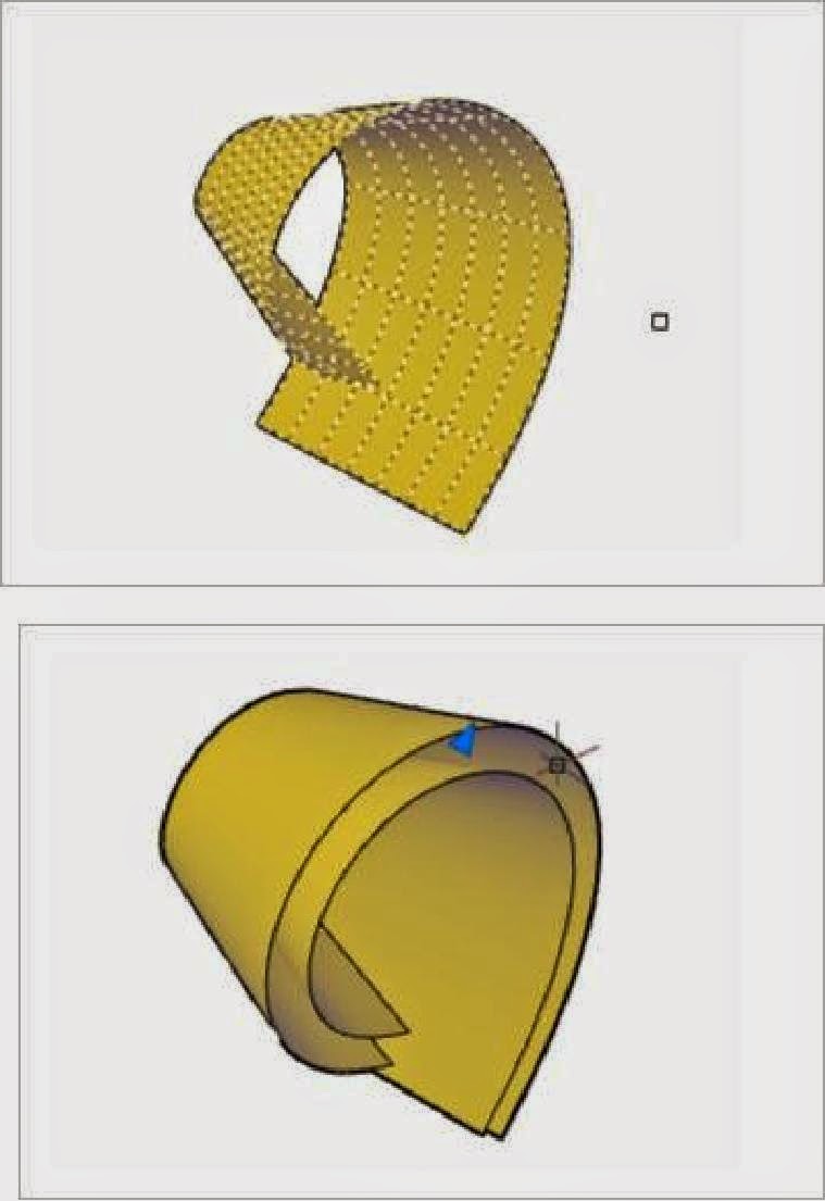
Creates a new surface or cap to close an open edge of an existing surface.

1. Type       SURFPATCH at the command prompt
                   Command: surfpatch


Offsetting Surfaces

Creates a parallel surface at a specified distance from the original surface.

1. Type       SURFOFFSET at the command prompt
                   Command: surfoffset

Editing Surfaces

Surface Fillet
1. Type       SURFFILLET at the command prompt
                   Command: surffillet


Surface Trim
1. Type       SURFTRIM at the command prompt
                    Command: surftrim


Surface UnTrim
1. Type       SURFUNTRIM at the command prompt
                   Command: surfuntrim


Surface Extend
1. Type       SURFEXTEND at the command prompt
                   Command: surfextend


Surface Sculpt
1. Type       SURFSCULPT at the command prompt
                   Command: surfsculpt


Convert to NURBS
1. Type       CONVTONURBS at the command prompt
                   Command: convtonurbs


Thursday, 5 February 2015

NURB Vertex Controls

Surface CV - Show
This command Shows NURB vertices.

1. Type          CVSHOW at the command prompt.
                      Command: cvshow

Surface CV - Hide
This command Hides NURB vertices.

1. Type          CVHIDE at the command prompt.
                      Command: cvhide

Surface CV Rebuild
Rebuilds control vertices of NURB surfaces or splines.

1. Type          CVREBUILD at the command prompt.
                      Command: cvrebuild

Surface CV Add
Adds control vertices of NURB surfaces or spline.

1. Type          CVADD at the command prompt.
                      Command: cvadd

Surface Remove
Removes control vertices of NURB surfaces or spline.

1. Type          CVREMOVE at the command prompt.
                      Command: cvremove


Surface Analysis

(1)Analysis Zebra

Projects parallel lines onto a model to help you analize surface continuty. The way the stripes line up where two surfaces meet helps analyze the tangency and curvature of the intersection.

1. Type          ANALYSISZEBRA at the command prompt.
                      Command: analysiszebra


(2)Analysis Curvature

Displays a color gradient onto a surface so you can evaluate the high and low areas of curvature.

1. Type          ANALYSISCURVATURE at the command prompt.
                      Command: analysiscurvature 


(3)Analysis Draft

Displays a color gradient onto a surface so you can evaluate if a model has adequate draft between a part and its mould.

1. Type          ANALYSISDRAFT at the command prompt.
                      Command: analysisdraft 


Designed By Blogger Templates